I have recently acquired a Spacesailer 24 as a Covid 19 escape. It has a refurbished Volvo Penta 2001 diesel, but the control panel is a bit of a mess. It would be useful to have some alarms, and I was wondering if anybody out there knows where I can get some replacement bulbs for the warning lights.
A good condition panel would also be nice, if you have one in your odds and ends locker.
Thanks!

Hi Yara
Instead of going back to the original (crappy ) Volvo panel I suggest that you make your own panel with off- the- shelf parts which in the end will be better.
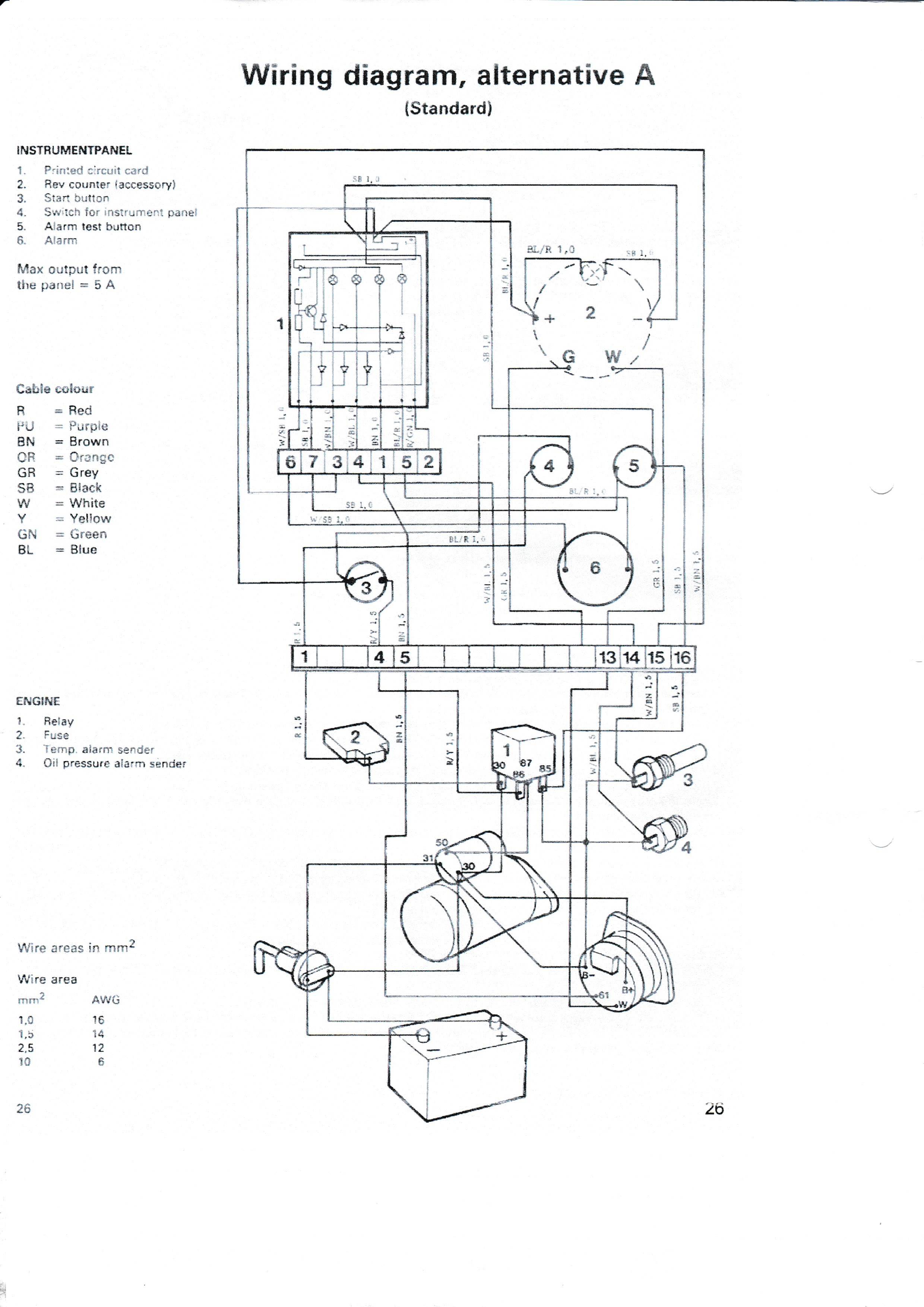
I have found a Volvo 2001 manual.
avdhoeff.home.xs4all.nl/zeilen_bestanden/Volvo-Penta-Type_2001-2002-2003T_Workshop-Manual.pdf
And have downloaded and scanned the wiring diagrams.

As is to be expected, neither of these are exactly what you have.
From your photo you have
Tachometer (or at least a big hole where it used to be)
Alarm
Alarm test switch
Instrument light switch
Combined on/off/ ignition switch
4 indicator lights ( Oil pressure. Engine high temperature. Charging. ? something else)
For what I have in mind I will go with diagram A
In diagram A, 4 is labelled "Switch for Instrument panel" I will call that the power on switch.
One thing that I picked up is the strange unit in both diagrams on the positive line directly out from the battery.
In diagram A the Positive and the negative feeds to the Starter motor solenoid are connected.
In Diagram B, the positive is connected to one terminal and the solenoid feed to the other.
Can anyone explain what this is? Battery isolator Switch?
I will work on a modified/ simplified/ cheapified improved set up and get back to you.
As you can guess, I have time on my hands.
gary
Thanks Gary. I cant work out diagram B either. No connection from the battery negative terminal. WTF? Lucky I have type A.
Suggest you go with a very simple waterproof cockpit panel. (plus a nav table panel with key switch and warning lights, and an engine room starter switch)
No tacho. (But if you want there are plenty of digital ones available.)
The cockpit panel would compose of:
1. an alarm buzzer (If present one works after a spray with WD 40, use it)
2. a a waterproof alarm test switch (you can eliminate this is you don't feel the need.
3. a waterproof starter push switch.
1 www.aliexpress.com/item/4000181141956.html?spm=a2g0o.productlist.0.0.53f27795ucnZBj&algo_pvid=67386eb2-2bbc-47c0-8d95-b36870f706dd&algo_expid=67386eb2-2bbc-47c0-8d95-b36870f706dd-36&btsid=0be3764315871040792287268e5e58&ws_ab_test=searchweb0_0,searchweb201602_,searchweb201603_
2 3.. Buy 10. surprisingly good. These switches would be the2 alarm test, the cockpit starter and the engine room starter. That is five of the same switches. (choose different colours if you like) www.aliexpress.com/item/32860925831.html?spm=a2g0o.productlist.0.0.46733930Ri3MBd&algo_pvid=4a9499f6-f8c0-4152-972c-54c209caf566&algo_expid=4a9499f6-f8c0-4152-972c-54c209caf566-32&btsid=0ab6f83a15870277937401352e7c7c&ws_ab_test=searchweb0_0,searchweb201602_,searchweb201603_
Then a main nav station Panel
This would have
1, an alarm.
2, an alarm test switch
4, key off/on/ignition switch.
When the key switch is on, the engine can be started from the nav station (as long as the throttle is opened) , the cockpit panel.
And I would suggest fitting another starter switch in the engine room to aid bleeding.
5. warning lights.
4. www.aliexpress.com/item/4000186887191.html?spm=a2g0o.productlist.0.0.73e871244y2AS0&algo_pvid=cebcc112-302c-4f12-9b6d-e56e29a40610&algo_expid=cebcc112-302c-4f12-9b6d-e56e29a40610-7&btsid=0be3743b15870229014075020ecd6a&ws_ab_test=searchweb0_0,searchweb201602_,searchweb201603_
Make the panels out of white cutting board.
Wiring diagrams to follow. With questions about warning lights.
gary
Here are some wiring diagrams.
For clarification I have shown the circuits together and separately.
I have made them as a complete diagram (1)
A diagram of the start circuit only (2)
A diagram of the complete alarm circuit (3)
A diagram of the Alarm Test circuit only (4)
A diagram of the Alarm Buzzer circuit only.
No1 is a complete diagram of panels minus the warning lights.
Those lights are not in either drawing, I have an idea of how they should be wired , but it is just a guess.
You should check how the originals were wired and what they were for.
The lines that I have identified as "To the top of Circuit Board have no colour code in the Volvo diagram..
You will have to identify them on site. (refer to the Volvo diagram as a guide)
I have added a fuse between terminal 1 and the key switch. You can eliminate that I you think it is not necessary.
I suggest you find the original fuse, check its condition and location. It should be in a place where you can find it easily at night.

No2. is the Engine off/on/start circuit. The wire colour codes are as per Volvo diagram.

No3 is the complete alarm/ alarm test circuit. Again with Volvo diagram wire colour codes.

No 4 is just the Alarm test circuit.

No5 is just the alarm buzzer circuit.

Have fun
Gary